Complex internal geometry
See turbine parts, housings, nozzles and structural assemblies without sectioning the component.
 Contact us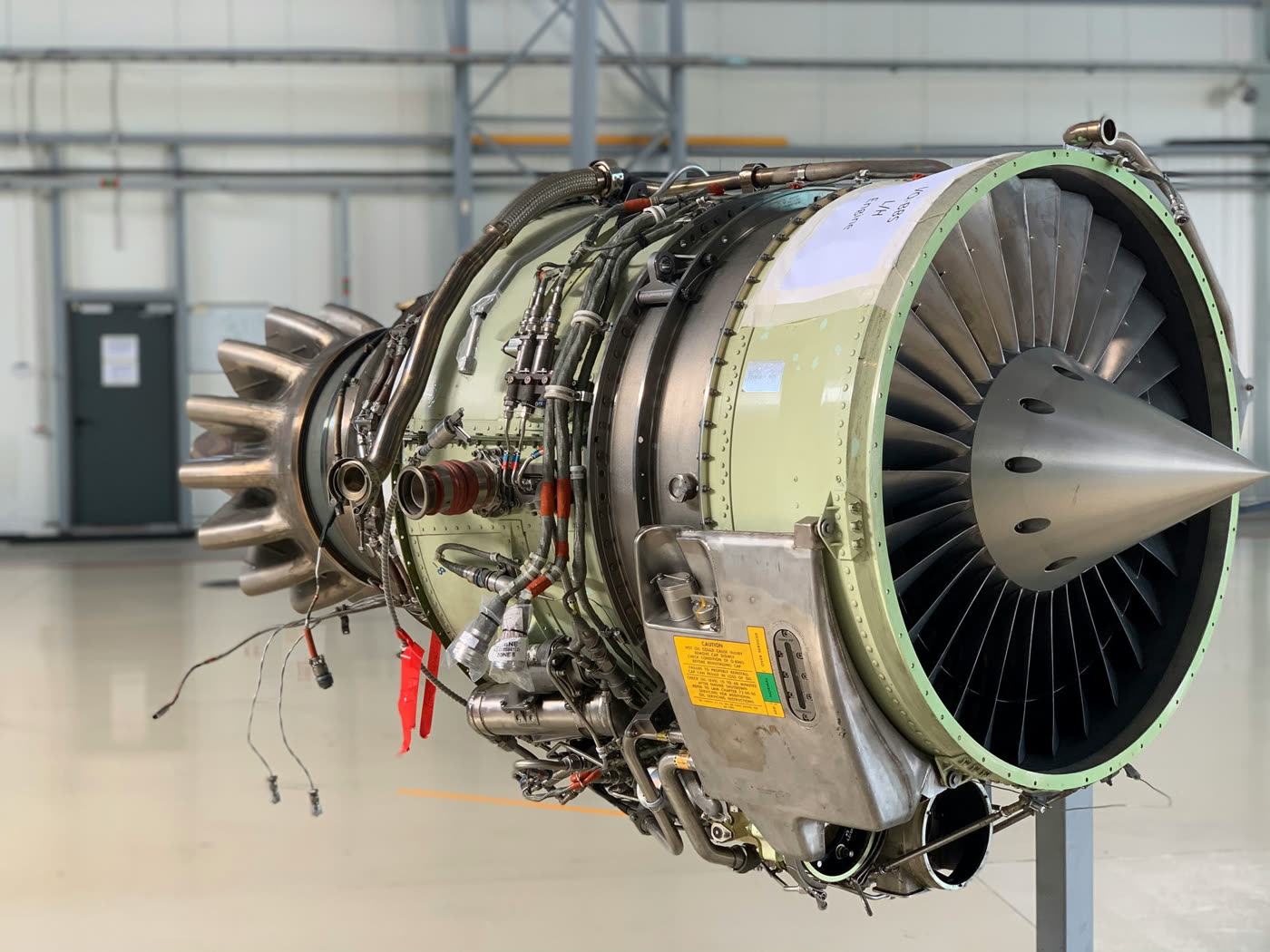
Aerospace industry
Custom requirements. Engineered solution.
From propulsion systems to avionics and structural assemblies, MQS engineers X-ray and CT solutions around the part, the defect, the material and the workflow.
Talk to an ExpertIndustry overview
Aerospace platforms operate under demanding performance and safety requirements. Porosity, cracks, inclusions, bond failures and dimensional deviations can remain hidden while still affecting reliability.
MQS supports aerospace applications with High-Energy X-ray and CT systems, MQX.NeVa industrial CT, MQX.NeVa-M microfocus CT and MQX.drIS cabinet-based digital radiography. The right configuration follows the component size, material, wall thickness, defect target and inspection workflow.
What aerospace teams need
One inspection strategy may need to support research, qualification, investigation and routine production QA.
See turbine parts, housings, nozzles and structural assemblies without sectioning the component.
Identify cracks, porosity clusters, inclusions and bond issues before they become larger quality problems.
Move from fine electronics and compact components to dense, thick-section assemblies.
Evaluate bonded interfaces, layered materials and reinforcement without cutting the part.
Support R&D, qualification, failure analysis and repeatable production QA with one inspection strategy.
Create repeatable results, image archives and reports that support technical review and audits.
Why MQS
Aerospace programmes need more than a machine specification. MQS starts with the component and inspection objective, then selects a proven platform and configures only what the application requires.
Source, detector, manipulation, shielding, automation, software and reporting are engineered as one inspection workflow.
Inspection concerns
Reveal internal cavities, clusters and density variation.
Identify structural breaks and hidden discontinuities.
Detect foreign material and internal anomalies.
Evaluate bonded interfaces and layered structures.
Check the position and relationship of internal features.
Use CT when layer separation, geometry review or metrology is required.
Application engineering
The inspection system should follow the engineering problem—not force the problem into a fixed machine.
Geometry, material and thickness
Defect type, resolution and evidence needed
Source, detector and CT or DR configuration
Manipulator, automation, analysis and reporting
A proven platform or configured solution
Product highlights
Select a labelled inspection area to see how MQS maps the component and risk to the right imaging workflow.
A · Propulsion
Turbine parts, housings and dense propulsion assemblies inspected for cracks, porosity, inclusions and internal geometry.
Application coverage
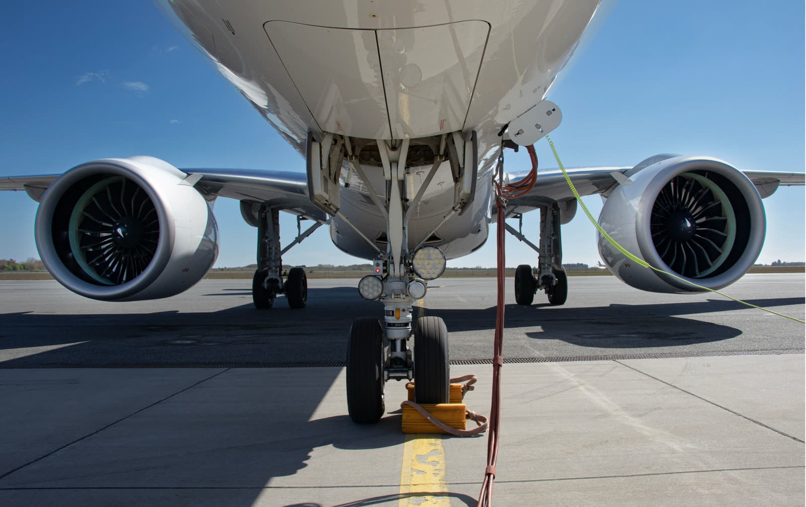
Engine and propulsion components, wing structures, fuselage frames, landing gear, control surfaces and tail sections.
MQX.NeVa-M · MQX.NeVa · MQX.drIS
Nose cones, avionics, wing-root structures, dense propulsion components, mounted assemblies and rear structures.
High-Energy X-ray & CT · MQX.NeVa · MQX.drIS
Avionics assemblies, rotor hubs, gearbox housings, powertrain components and tail structural sections.
High-Energy X-ray & CT · MQX.NeVa · MQX.NeVa-M
Payload fairings, interstage joints, motor casings, propellant sections and dense propulsion nozzles.
High-Energy X-ray & CT
Safe, traceable inspection
AERB-aligned safety architecture for shielded inspection systems.
ASTM-aligned workflows where applicable to the component and inspection objective.
Inspection records and reporting that support customer review and audits.
Resources
Move from an application to the relevant platform information, or share the component with our engineering team.
Bring us the inspection challenge.
Share the component size, material, thickness, defect target and inspection workflow.
Share your part, material and defect type — our engineers will recommend the right MQS system.